
In my last post we recreated the simple Blink program from Arduino using the built-in LED on the board. The program simply turned the LED on for one second and then off for a second.
Today we will add three LEDs to the breadboard, along with resistors to keep the current down to prevent burning them out. We will use 3 separate pins on the board so we can control each of the LEDs independently. Here are photos of the board.

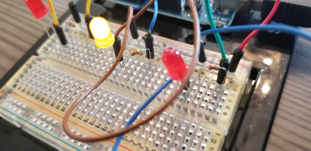
For the build on the breadboard, note that I use a single jumper wire from the ground (GND) pin next to pin 13 on the board, to the (-) row on the breadboard. That way I can use the same ground for all three LEDs. For the voltage side, we need each LED to be operated from a different pin as described below. The flow is such that each pin has a jumper to one end of a 330-ohm resistor. The other end of the resistor is in a row of the breadboard that connects to the LONG leg of the LED. Note that if you connect the short end of the LED in this way, the light will not work. Then we have another jumper that connects the short leg of the LED to the ground (-) row of the breadboard.
Paul McWhorter has a great video tutorial on how LEDs work and another on how to use a breadboard. At the end of the breadboard tutorial, he gives the challenge to wire up and program the Arduino to control three separate LEDs, making each blink a different number of times. This is the code I used to do so. In the next tutorial, we will learn to write our own function that will allow us to remove a lot of the duplicate code. For now, let’s see how to blink the three LEDs. In this lesson, we will learn about global variables.
int redLED1 = 13;
int yellowLED = 12;
int redLED2 = 11;
// the setup function runs once when you press reset or power the board
void setup() {
// initialize digital pin LED_BUILTIN as an output.
pinMode(redLED1, OUTPUT);
pinMode(yellowLED, OUTPUT);
pinMode(redLED2, OUTPUT);
}
// the loop function runs over and over again forever
void loop() {
// red 1 blink 3 times
digitalWrite(redLED1, HIGH);
delay(500);
digitalWrite(redLED1, LOW);
delay(500);
digitalWrite(redLED1, HIGH);
delay(500);
digitalWrite(redLED1, LOW);
delay(500);
digitalWrite(redLED1, HIGH);
delay(500);
digitalWrite(redLED1, LOW);
delay(500);
// yellow blink 2 times
digitalWrite(yellowLED, HIGH);
delay(1000);
digitalWrite(yellowLED, LOW);
delay(1000);
digitalWrite(yellowLED, HIGH);
delay(1000);
digitalWrite(yellowLED, LOW);
delay(1000);
// red 2 blink 5 times
digitalWrite(redLED2, HIGH);
delay(500);
digitalWrite(redLED2, LOW);
delay(500);
digitalWrite(redLED2, HIGH);
delay(500);
digitalWrite(redLED2, LOW);
delay(500);
digitalWrite(redLED2, HIGH);
delay(500);
digitalWrite(redLED2, LOW);
delay(500);
digitalWrite(redLED2, HIGH);
delay(500);
digitalWrite(redLED2, LOW);
delay(500);
digitalWrite(redLED2, HIGH);
delay(500);
digitalWrite(redLED2, LOW);
delay(500);
}
int redLED1 = 13;
int yellowLED = 12;
int redLED2 = 11;
These are our global variables. Global means that they can be read and used in all of the functions in our program. They can be read in setup, loop, and any functions we may write ourselves. As I only have red and yellow LEDs in my kit, that’s what I will here. You can name the variables whatever you want, as long as you make it valid within the rules of the programming language. My variable names are redLED1, yellowLED, and redLED2. I like to make my names very obvious so when I or someone else reads the code later, it’s easy to understand. The “int” part simply means that these are integers like 1, 2, 100, or 365. We are using ints because these variables will represent pins on the Arduino board. I will be using pin 13 for redLED1, pin 12 for yellowLED, and pin 11 for redLED2. Here is a great page with the rules and variable types to help with the rules and data types.
In the last lesson, we used the LED_BUILTIN constant variable to blink the LED on the board. Now we are setting the pinMode in setup() for all three LEDs.
pinMode(redLED1, OUTPUT);
pinMode(yellowLED, OUTPUT);
pinMode(redLED2, OUTPUT);
Each line sets the pinMode for a pin, so the first line set redLED1 (pin 13, remember?) to be OUTPUT. The next two lines do the same for pins 12 and 11. Simple so far, right?
Now for the loop() function.
// red 1 blink 3 times
digitalWrite(redLED1, HIGH);
delay(500);
digitalWrite(redLED1, LOW);
delay(500);
This looks a lot like the original Blink program, but with some differences. Now, we are passing in the variable name for the first LED, redLED1, instead of LED_BUILTIN. We have this code copied three times, once for each time we want the LED to blink. As I wrote in the comments // red 1 blink 3 times. Note that the delay is 500 milliseconds (one-half second) for when the LED is on, and 5oo milliseconds when the LED is off.
Then we do the same thing for the yellow LED, but we will blink it twice with a delay of one second on and one second off.
// yellow blink 2 times
digitalWrite(yellowLED, HIGH);
delay(1000);
digitalWrite(yellowLED, LOW);
delay(1000);
Finally, we blink the second LED, redLED2, five times, each with a half second delay.
// red 2 blink 5 times
digitalWrite(redLED2, HIGH);
delay(500);
digitalWrite(redLED2, LOW);
delay(500);
This code runs in the loop() function, so it will continue to blink in the same sequence:
Red 1 on and off three times with a half-second delay.
Yello on and off two times with a one-second delay.
Red 2 on and off five times with a half-second delay.
Resources:
Code in text format (Google Drive)
Code in Arduino Sketch format
Previous Lesson: Arduino Lesson 1
Next Lesson: Arduino Lesson 3 – New Function