
So far we’ve been writing digital signals to control an LED. Today we will use analogWrite to do it in a similar way, but now we will use Pulse Width Modulation (PWM) over an analog pin. I highly recommend watching Paul McWhorter’s video on PWM for a detailed explanation of how it works.
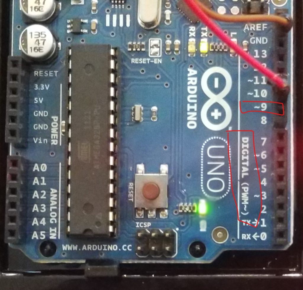
My Arduino Uno offers digital pins 2 – 13. Note in the photo below that pins 3, 5, 6, 9, 10, and 11 each have the ~ symbol next to it. This indicates that this pin can be used for PWM. In this build, I’m using pin 9.
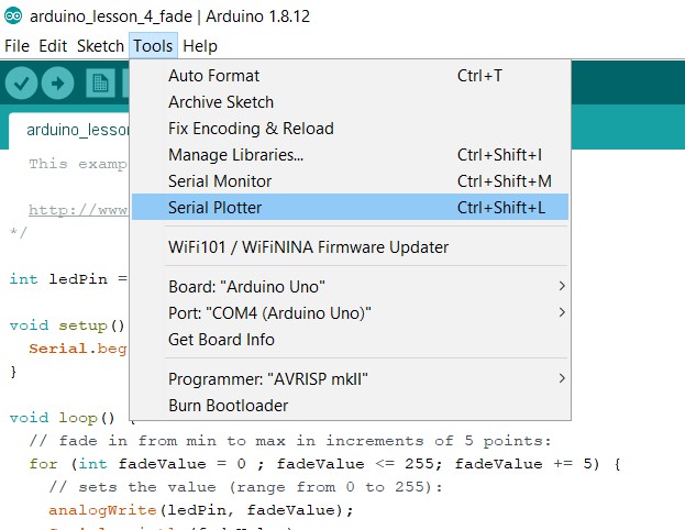
Today, not only are we going to do an analog write, we will also take a look at the Serial Plotter and Serial Monitor, tools that are included with the Arduino IDE. The plotter lets visualize the output while the monitor writes messages out in a readable format.
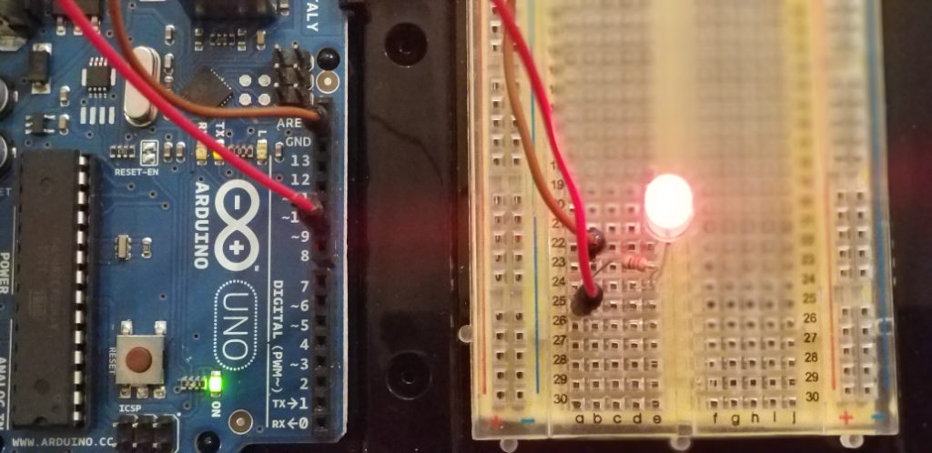
The circuit is much the same as we’ve done for previous lessons in that we have an LED connected through a 330-ohm resistor. Digital pin 9 is connected to one end of the resistor and the long leg of the LED is connected to the other end of the resistor. The short leg of the LED is connected to ground.
The code for this lesson comes from a combination of the Arduino Fading and Arduino AnalogReadSerial examples found in your Arduino IDE. I simply added the Serial.begin and Serial.println commands from AnalogReadSerial and added them to Fade. Then I added more code to change the output. Let’s take a look at the code.
int ledPin = 9;    // LED connected to digital pin 9
 void setup() {
   // declare pin 9 to be an output:
   pinMode(ledPin, OUTPUT);
   // initialize serial communication at 9600 bits per second:
   Serial.begin(9600);
 }
 void loop() {
   // fade in from min to max in increments of 5 points:
   for (int fadeValue = 0 ; fadeValue <= 255; fadeValue += 5) {
     // sets the value (range from 0 to 255):
     analogWrite(ledPin, fadeValue);
     Serial.println(fadeValue);
     // wait for 30 milliseconds to see the dimming effect
     delay(30);
   }
 Serial.println("****************");
   delay(500);
 // fade out from max to min in increments of 5 points:
   for (int fadeValue = 255 ; fadeValue >= 0; fadeValue -= 5) {
     // sets the value (range from 0 to 255):
     analogWrite(ledPin, fadeValue);
     Serial.println(fadeValue);
     // wait for 30 milliseconds to see the dimming effect
     delay(30);
   }
 Serial.println("*****************");
   delay(500);
 }
Note that we are setting the global variable ledPin to 9. In setup() we set pinMode on our ledPin to be OUTPUT, and we have a new command, Serial.begin(9600); From the Arduino reference page:
Sets the data rate in bits per second (baud) for serial data transmission. For communicating with Serial Monitor, make sure to use one of the baud rates listed in the menu at the bottom right corner of its screen. You can, however, specify other rates – for example, to communicate over pins 0 and 1 with a component that requires a particular baud rate.
In loop() we are using two “for” loops to create the fade effect. The first “for” loop will increment from 0 – 255 in increments of 5. In previous code, we used counter++ to increment our counter by 1 for each pass through the code. Here, we are using fadeValue += 5 in the first pass and fadeValue -= 5 in the second pass to go from 255 – 0. So logically, the first loop counts from 0 – 255, using 5, 10, 15, etc. up to 255, then the second loop counts down from 255 – 0, using 255, 250, 245, etc. to 0. There is a 30-millisecond delay after each write so we can watch it smoothly transition between values.
Next, we need to understand the parameters for analogWrite. Similar to digitalWrite, the first parameter is the pin number and the second parameter is the value to pass to the pin. For digitalWrite we passed either HIGH (on) or LOW (off) to the pin. However, for analogWrite we pass a value from 0 – 255, where 0 is equal to LOW (off) and 255 is equal to HIGH (on). The cool thing is that we can set other values as well. So a value of 127 would be approximately half as much as 255, making the LED about half as bright as it is at HIGH. What we are doing is changing the voltage on the pin from 0 – 5v, so a value of 0 in the value is 0 volts and a value of 255 is 5 volts. Varying the voltage will vary the current flowing through the circuit, therefore varying the brightness of the LED. Sweet, right?
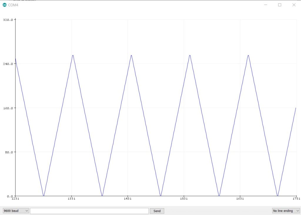
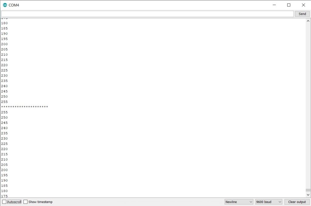
Did you notice the new code after analogWrite? Serial.println(fadeValue); will write the value of fadeValue back to our Arduino and we can show that value in our IDE. Each time the value in our “for” loops goes up or down, we record that back so we can see the value in the Serial Plotter or the Serial Monitor (see screenshots below).
So the flow of the code is to first increase the brightness of the LED from off to full brightness, writing each value back to the Arduino IDE. Then decrease the brightness back to 0. As we are in the loop() function, this will repeat over and over. I’ve also added Serial.println(“*****************“); and a delay of 500 milliseconds after each “for” loop. This will not show up on the Serial Plotter, but it will print out to the Serial Monitor, making it easier to see where our loops begin and end.
One thing to remember is that you cannot have the Serial Monitor and the Serial Plotter both open at the same time. You can only open one at a time.
Resources
Previous Lesson: Arduino Lesson 3 – New Function
Next Lesson: Arduino Lesson 5 – Basic Pushbutton